SOLIDWORKS for Fabrication
In today’s DIY centric culture, people of all ages prefer to put on their handy-man hat and work on household refurbishments or repairs. In fact, most people also like to build additions to their home like patios or even BBQ grills etc, but it always is a massive hassle to work with a team to get the job done. This is mainly because people have neither a solid plan on paper nor a cost analysis of how much it would cost. This is where SOLIDWORKS can help fulfill both of these issues.
Discussed below is how one can use SOLIDWORKS to:
- Take an idea from Paper into a 3D Model.
- Make the model compatible for Fabrication.
- Make changes to iterate the best design.
- Create blueprints that anyone can follow to help build the project.
- Generate a Bill of Materials for a Quote from a vendor.
Take an idea from Paper into a 3D Model
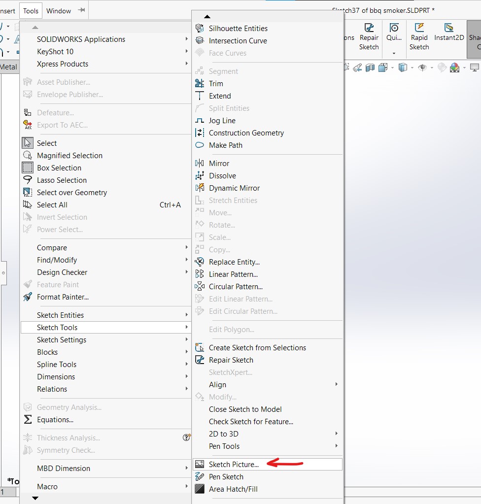
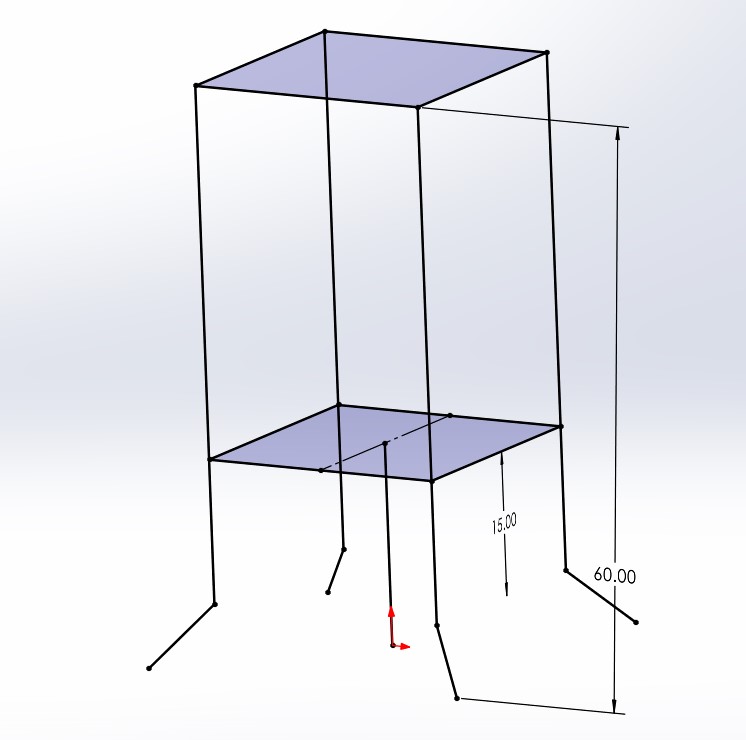
When it comes to bringing an idea from your imagination or paper into SOLIDWORKS there are a number of key techniques that could help speed up the process. firstly, you can always scan the sketch that you have drawn on paper and imported as a reference image within SOLIDWORKS to trace it into solid geometry, another method is using 3D sketches in which you can build the entire model more or less one sketch by using the elements and sheet metal. other good practices include and showing fully defined sketches at all stages of the modeling process.


Make the model compatible for Fabrication
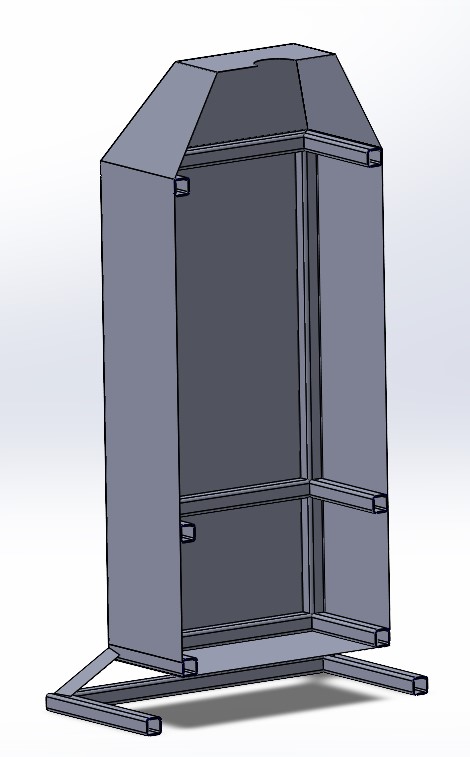
Keeping in mind this is a model that we plan on fabricating in real life there are a couple of features that we need to keep in mind, firstly any structural Steel piping will have to be built using weldments, send this automatically creates the cut list within SOLIDWORKS. In case of any sheet metal bending, it's better to use the sheet metal segment within SOLIDWORKS to account for sufficient relief in the material as well as corner treatment to ensure the designed part is physically manufacturable without any hiccups. As of SOLIDWORKS version 2022, there is no feature that can help in nesting which is the automatic most optimal orientation and packing of components to be cut from a sheet of sheet metal to help reduce the total usage of raw material.
But there are third party software providers which have created SOLIDWORKS add-ons to solve this issue.
Make changes to iterate the best design
Once the initial model is ready it is now time to test it Virtually for function as well as collisions between individual components. Before material is cut and prepared for fabrication it is crucial to verify that the design will work to fulfilled intended need in real life, this can be done by the help of motion studies in SOLIDWORKS. These helps understand the motion of all of the components of the model as well as their relative motions to each other.
using the power of SOLIDWORKS motion week and then run interference detection while the model is in motion this is extremely crucial since this allows us to identify any collisions between the components in a dynamic state of the model.

Create blueprints that anyone can follow to help build the project
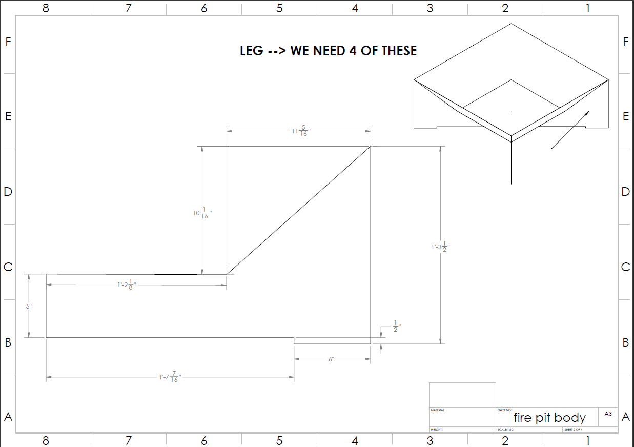
One of the key reasons why a lot of time and capital is wasted during the fabrication phase is incorrect blueprints. SOLIDWORKS helps eliminate this issue by creating blueprints that are directly linked to the verified 3D model, the user only has to choose the layout of the different perspective views as well as location of the dimensions. This can be then printed into a blueprint to help speed up the fabrication and installation of the project.
At this stage it is also a good idea to create exploded views as well as section views of the use of the model to better understand the internal workings and assembly components of the product.


Generate a Bill of Materials for a Quote from a vendor
Once the 3D model is complete and verified using interference detection as well as motion studies in SOLIDWORKS, it's time to create a cut list as well as materials for the given project.
from the previous steps we have already understood how creating the components using weldments and sheet metal help SOLIDWORKS understand and automatically add these components into the cut list along with their dimensions and specifications. this includes all of the pipe as well as structural Steel components that will be used within the project, the only components which do not get adequately mentioned are the sheet metal components. the sheet metal components will have to be manually computed for their quantity this is done by first nesting the required sheet metal parts on a standard size of sheet metal to compute the total number of metal sheets that we will need for the project. at this stage we can now supply the cut list information as well as the the total number of metal sheets needed for local vendor you can then proceed to give us a quote on the total cost of raw material.
Getting a more accurate final Quote
Once you receive the final code from the vendor it's up to us to now Tally and the total cost of additional labor if any, as well as heavy equipment needed for lifting and cutting if any. these are crucial sense at time is if the product has to be installed on site the total cost of labor and workmanship can add up pretty quick. there are two methods to do this, the first method is quite rude and only involves marking up the vendor’s price tag by given percentage as your final quote, but this is quite inefficient. the better way to estimate such costs is using specific software to handle the heavy lifting of such cost estimation example being Tekla Power Fab, software like this can even take into account any sort scaffolding of during installation into the final Quote.


.png)

